Will Your Mold Fit a Used Injection Molding Machine? Check These Dimensions
A practical mold-to-press fit checklist covering tie-bar clearance, mold thickness, daylight, opening stroke, platens, ejector and nozzle alignment before a used-machine purchase.
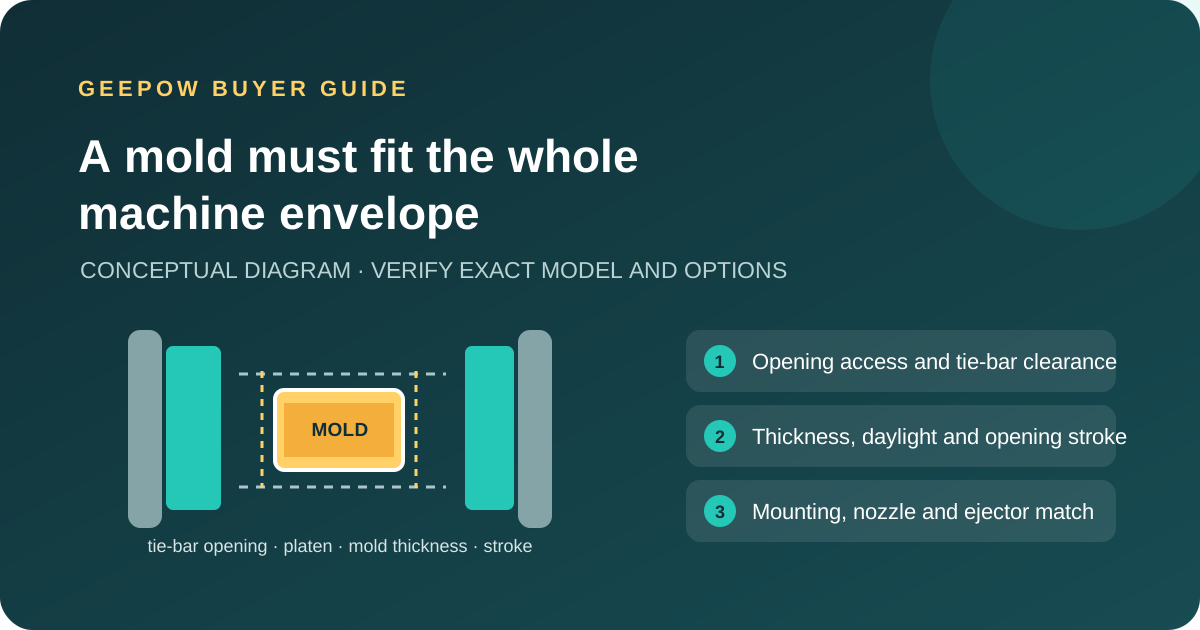
Short answer: do not decide mold fit from clamping tonnage or the mold’s outside dimensions alone. Compare the exact mold envelope and mounting requirements with the exact press configuration: usable entry space, tie-bar opening where applicable, mold-thickness range, daylight, opening stroke, platen layout, ejector and nozzle interfaces. Then confirm access for the actual handling and automation plan.
A machine can have ample clamping force and still reject a tool because it cannot enter the clamp unit, reach the required installation height, open far enough to release the part or connect correctly to the ejector and nozzle. Start with drawings and nameplate-specific manufacturer data; use a physical fit check before committing whenever possible.
Collect the mold facts first
Use the mold drawing and measured tool—not a rough estimate from product dimensions. Record the maximum width and height including clamps, connectors, hydraulic manifolds or sensors that protrude during installation; total mold thickness at its operating setup; mold weight and center of gravity; locating ring and sprue-bush dimensions; ejector requirements; and the part/robot clearance needed at open position.
Match each constraint to the machine
| Fit check | Evidence to request | Pass condition |
|---|---|---|
| Entry and clamp opening | Machine layout showing tie-bar spacing or the unobstructed opening for a tie-bar-less clamp; note removable bars only if the OEM permits removal | The complete tool envelope can enter and be positioned safely, with the planned clamps and connections |
| Mold thickness and daylight | Minimum and maximum mold thickness, adjustment range and maximum daylight for the exact machine | The tool fits the adjustment window and opens to the required setup height |
| Opening stroke | Available opening stroke plus the actual mold opening and part-removal travel | Parts, cores and robot can clear the tool without exceeding the machine’s rated travel |
| Platen and mounting | Platen dimensions, T-slots or threaded pattern, locating-ring seat and clamp area | Safe mounting is possible without obstructing tie bars, ejector or safety devices |
| Ejector interface | Machine ejector position, rod pattern, stroke and force versus the mold drawing | Rod engagement and travel match; extra plates or adapters are engineered and approved |
| Nozzle and sprue | Nozzle radius/orifice, nozzle reach and mold sprue-bush geometry | Correct contact and flow path are available without a collision or unsupported adapter |
| Weight and automation | Moving-platen/mold-load limits, tool lifting points, robot reach and open-door extraction route | Tool handling and part removal stay within manufacturer and site limits |
Read the technical table as a set of limits
Manufacturer documents commonly list several separate dimensions. Haitian’s Zhafir Jenius technical table, for example, identifies mold-thickness range, spacing between tie bars, opening stroke, ejector stroke and force as distinct parameters. A buyer should match each line to the corresponding tool requirement, rather than treating one large platen or clamp-force number as proof of compatibility.
Clamp architecture matters too. ENGEL describes its victory range as tie-bar-less, with a barrier-free mold area. That illustrates why buyers should confirm the actual clamp design before applying a tie-bar measurement to every press. A tie-bar-less opening still has limits: platens, columns or guards, mold mounting, machine stroke and safe access must all be checked on the exact machine.
Use this pre-purchase checklist
- Get the mold’s controlled drawing and verify every installation dimension, including any connector or clamp that must remain attached.
- Photograph the press nameplate, clamp unit and platen; record the full model, year, serial number and options.
- Match the tool’s thickness to the OEM mold-height range and calculate the open daylight needed for part removal.
- Compare the complete tool envelope with tie-bar spacing or actual tie-bar-less access; consider how the mold will be carried into the machine.
- Check mounting, locating ring, sprue bush, ejector pattern/stroke, mold weight and moving-platen rating.
- Review automation, core connections, safety gates and robot entry against the intended setup—not merely the machine’s advertised tonnage.
- If any value is close to a limit, ask the OEM or a qualified tooling engineer to review the drawings and verify with a physical trial.
Common reasons a paper match fails
Catalog data can describe a base machine while the used press has options, later alterations or a different clamp configuration. A mold may fit through the bars but exceed thickness or daylight limits; fit the platens but misalign the ejector; or close correctly but leave inadequate space for a robot or side-core hoses. Removable tie bars are not a workaround unless the manufacturer confirms the procedure and the production arrangement remains safe.
This checklist is for screening standard mold installations. Magnetic clamping, rotary tables, multi-component tools, vertical presses and custom bolsters add interface-specific constraints. Confirm those separately; the dimensions here do not certify a specific machine or mold pairing.
Frequently asked questions
Is tie-bar spacing the same as the maximum mold size?
No. It is one access dimension for a tie-bar machine. Mold thickness, platen mounting, opening stroke, ejector and handling access remain separate checks.
Can I choose a press by tonnage first?
Clamping force matters for the process, but it does not prove the mold can be installed. Confirm geometry and interface constraints in parallel with the required clamping force.
What if the mold fits only after adding a spacer or bolster?
Recalculate mold height, daylight, stroke, ejector engagement and load limits with the proposed plate. Have the design reviewed and tested; do not assume an adapter preserves every rated limit.
Send the mold and machine details for a fit review
Share the mold drawing, weight, installation height, robot plan and press nameplate when you ask GEEPOW about a used machine. You can review injection molding machine options and see the separate checks in our magnetic-clamp mold guide and platen-parallelism inspection guide.