
Side-Entry Mould Checks for Used Two-Platen Machines
Buying a used two-platen injection moulding machine? Verify the tie-bar or platen option, clear tool path and return to production before committing.
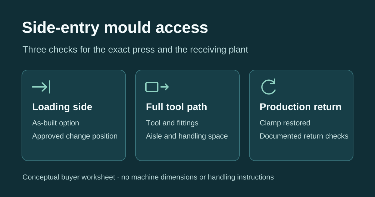
If a low ceiling rules out lowering the tool into a used two-platen injection moulding machine, make side-entry access a purchase condition. Ask the seller to prove that the offered press opens a clear path on the side your factory can use, that the complete tool can pass through it, and that the clamp returns to its normal production configuration after the change.
Conceptual buyer worksheet. Verify the dimensions and change procedure against the exact press and site.
Find out what actually creates the opening
FCS reports a customised two-platen LM-900 built for a plant where ceiling height prevented top loading. Its optional tie-bar puller moved one bar out of the way for horizontal mould entry. Ask the seller which side the offered press clears and whether it still has all the parts for that option. The same model name can appear on a listing with a different configuration.
Chen Hsong documents a different solution on a custom Supermaster SM3600-TP delivered to a German processor. Three tie bars were longer than the fourth. In the mould-change position, the moving platen could travel beyond the shorter bar, clearing one corner for side entry. This 3,600-tonne example sits above the 500–3,300 metric-tonne buying range discussed here. Use the two designs to frame your question: what creates access on the exact unit you might buy?
YIZUMI also lists automatic tie-bar retraction as an option in its DP Series literature. Ask for the option record and a demonstration on the machine you are considering.
Check the route in two machine positions
| What you need to decide | Evidence to request | When to keep the purchase conditional |
|---|---|---|
| Will this press open the correct side? | The full model and serial, an option record or machine-specific drawing, and a technician’s record of the clear opening in the documented mould-change position. Identify the side on the drawing. | The seller sends only an image of a similar machine, or the option clears the opposite side from your usable aisle. |
| Can the whole tool travel from the aisle to the platens? | The tool drawing with protruding fittings, its weight and the proposed handling arrangement. Have your tooling and handling teams compare the full transfer path with the machine, guards, adjacent equipment and available headroom. | The nominal opening is wide enough on paper, but the tool needs to turn past a guard or the handling equipment needs space that the drawing has not allowed for. |
| Can the press return to production after the change? | A qualified technician’s demonstration and record of normal clamp configuration being restored. Record the agreed checks for re-engagement or locking, machine indications and guards or interlocks required on the offered press. | The video stops when the opening is clear or the seller cannot document the return checks against the machine instructions. |
For example, a seller can demonstrate an access option on the service side while your available aisle serves the operator side. Ask for an updated orientation drawing before accepting the match. Turning the machine around introduces new access and service questions. Have those checked at the receiving plant.
Put both demonstrations in the quotation
Ask the seller to show the exact machine reaching its documented change position and returning to its normal production configuration. Separately agree whether the transfer itself will be witnessed with your tool or a documented substitute. If final fit will only be checked after installation, name the responsible technician and record the unresolved clearance, acceptance evidence and agreed remedy in the purchase terms.
Use the mould-fit guide for separate checks on mould thickness, daylight, platen mounting and the ejector interface. Verify the machine’s moving-half load and balance limits separately with your tooling engineer. Use the cell layout planning guide to include the aisle, headroom and adjacent equipment on the receiving-site drawing. The machine maker’s instructions and your site’s qualified team govern tool handling and changes to the clamp configuration.
Questions buyers ask
Does the tie-bar spacing prove a mould will enter from the side?
It describes one dimension of the clamp. For side entry, confirm the clear opening in the approved change position and the path of the assembled tool and its handling equipment from the aisle to the platens.
Can a video establish that the tool will fit my plant?
A continuous video can show the offered press’s configuration and operation on the seller’s site. Match the tool and change position to your own dimensioned aisle, headroom and handling layout before signing off.
See GEEPOW’s used injection moulding machine sourcing page or send your side-entry mould requirements. Include the offered model or target clamp force, the mould drawing and weight, the intended loading side and the receiving plant’s aisle and overhead limits.